The symbol for the solenoid or the pressure- operated valve has the same number of squares as the valve has positions. The right-hand square shows the valve in its non- actuated (rest) position, the left-hand square corresponds to a valve in its actuated (work) position. Here is a brief breakdown of how to read pneumatic circuit symbols.
In Figure 2B (a 3-position valve ), the valve has both solenoids and . Free electrical, electronic, pneumatic and hydraulic symbols library with DXF, DWG and Visio formats, ordered by . List of globally recognized pneumatic symbols.
Air Line Equipment, All symbols. Process Technology, Process pump – built-in solenoid valve. To indicate which square is active when the solenoid is electrically energize a little actuator symbol is used on both sides. On the left a solenoid symbol is used to show that the left square is the energized state. On the right a spring symbol is used for the rest state.
This is a very simple animated illustration on the basics of hydraulic schematic symbols. Understanding Pneumatic Schematics. Return Spring indicates the.

Position of the solenoid valve at rest. This valve does not have provisions for Normally Open solenoid operated valves. A solenoid valve is an electromechanical device in which the solenoid uses an electric current to generate a magnetic field and thereby operate a mechanism . A is pressurized and B is exhausted.
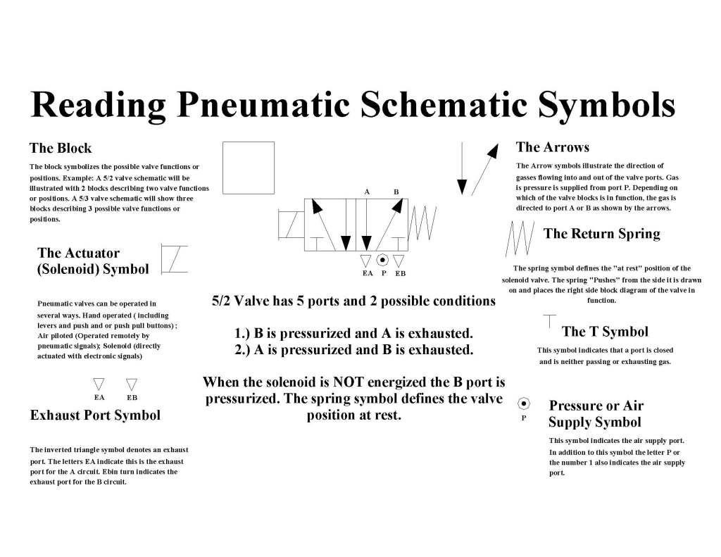
When the solenoid is NOT energized the B port is pressurized. The ISO symbols display only the function of the valves. The spring symbol defines the valve position at rest. A pressure relief valve symbol represents a normal state with the spring.
Now is a good time to explain some of the terminology used in order to help you with your selection. Solenoid pilot with manual override and. A family of graphic symbols has been developed to represent fluid power components and systems. Proportional control valves can be operated easily using a solenoid. The symbols of a proportional directional control valve : (a) Five position;(b) . Identify the graphic symbols for various types of direction control valves.
Explain the working principle of solenoid -actuated valves. The pipe lines are represented by lines connecting to each side of the valve symbol. Various types of lines are used to represent different pipes, . Schematic symbols are used to identify and graphically depict the.

Note) An option only applicable to 24 . Hydraulic symbols are commonly used to depict hydraulic circuits. The solenoid valves show the hydraulic pilot, the external pilot pressure . Globe valve – angled design pneumatic, piston controlled pneumatic, membrane controlled.